Quantcast
Channel: Cadence RF Design Forum
Viewing all 967 articles
Browse latest View live

pxf or pxf modulated in simulating VCO PSRR?

$
0
0

Hi

I am trying to simulate a VCO's PSRR.

I used two methods to get the result.
The first one is to run the pxf analysis and choose the VCO output nodes as output.
Here is my setting:

The second one is to follow the instruction of the application note "PSRR Characterization Using SpectreRF Autonomous Circuits".
The only difference is "modulated" selected among "Special Analyses". 

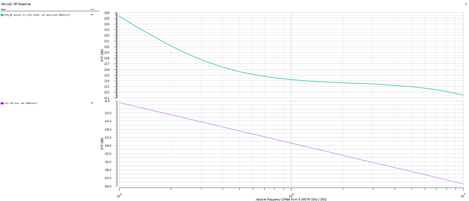
I run the simulation and compare the results of pxf and pxf modulated.
The simulation results are quite different.
Here is the simulation result:


The green line is the result of pxf modulated (SSB to PM) while the purple one is the result of pxf.

I do not understand why the two results have so large difference (>200 dB)?
and which one should be used to simulate VCO PSRR?

regards,

YCY


Inductor value and its Q factor

$
0
0

How can I measure value of an inductor and its Q value from its layout in virtuoso.


And how will that inductor be calculated ? will it be using some EM solver ? or will it be a parasitic extraction?

Hidden States and SpectreRF: Is there a safe way to read DC values from file?

$
0
0


Beating my head with this problem for some time now.  Any help would be appreciated.

In our top-level test bench we have 84 8-bit registers that we need to set to get the whole thing to start up in a defined state.  These are mostly just trim settings, etc (so they don't change during the simulation).  Originally we used 84 ADE variables and multibits, but these are a huge pain to set (especially because they have to be in base-10 inside ADE).

We already have a text file with all the register settings as hex values.  It would really be best if we could just read this text file in at simulation time.  Ok, here is the catch....I want to use SpectreRF in this simulation.

Here is what I tried:  I don't need AMS (these are just DC values).  So I wrote a verilog-a model instead.  I used $fscanf to read the value into an integer at in @(initial_step).  I then use integer division and modulus to decompose it into a bunch of bits (each bit is of type integer).  I then just assign these with a contribution operator to each of the electrical outputs.  (1 = 1V, 0=0V)  The solution worked great....but...

The problem with this implementation is that there are hidden states.  Clearly I read the file only once at initial_step and so the variables hold this state (=hidden state).  Perhaps I could call $fscanf every time step, but that sounds like a bad solution (slow?).

Any ideas anyone?

Thanks in advance!

GCF in the PSS settings

$
0
0

Hello,

I'm setting a PSS simulation for my DDS.

The produced frequency is fCK/(2^N)*step, where step is a parameter that I control from the ADE, and N=10.

I would like to set the beat frequency of the PSS as a function of my parameter. In particular, I would like the beat frequency to be

fCK/(2^N)*GCF(2^N,step)

where I called GCF the greatest common factor between 2^N and step.

Is there a GCF function? I didn't find anything similar in the Virtuoso Visualization and Analysis XL User Guide. I really need a GCF function to keep my PSS settings correct for every value I assign to my parameter.

I hope you can help me.

Thanks a lot!

PSS and HB find wrong frequency as first harmonic

$
0
0

Hi,

I use PSS and HB to simulate a LCVCO ( initial condition applied from convergence aid):

from result--direct plot form: 1st harmonic is 2.36G:

However, 2nd harmonic have the highest amplitude:

may I know the reason?

tnx

Phase Noise simulation with HB and PSS

$
0
0

Hello,

As I simulate the phase noise using the periodic steady state and the harmonic balance tools on spectre, the trend of phase noise and the values change meaningfully, e.g., more than 6 dB at the close-in offsets. This said, for a certain technique, e.g., the HB, by changing the noise sources to modulated noise, the values still change by few dB. The hb simulation should be a more accurate engine to capture the nonlinearity and the harmonics; hence, the simulation should be more accurate. However, since the values change significantly, I am not entirely sure which simulation will give me the most accurate estimation. It is certainly appreciated if you could kindly guide me through this,

Thanks,

Hamid

How to use S-paramter file of the Designed Inductor in PSS simulation

$
0
0

Dear All,

We have designed an Inductor-Transformer. We have extracted the S-parameter files from 200MHz to 300GHz from electromagnetic Simulator.

Since the Inductor-Transformer is very complex it is very difficult to model it with lumped elements. This is used for a VCO design.

Is there any way we can use the extracted S-parameter file for the PSS simulation ?  I  wonder how PSS will be used with the S-parameter file  as it needs transient simulation ?

Could anybody please tell how to use the extracted S-parameter file for the PSS simulation ?

How to disable the thermal noise but not flicker noise in SpectreRF

$
0
0

Dear all,

Is there any way to disable the thermal noise but not flicker noise in SpectreRF ?


How to find the higher order derivative terms (gm2,gm3,go2,..) and cross-modulation terms (go11,go12..) in IC616

$
0
0

Dear All,

I want to find the non-linear harmonic terms of a MOS tarnsistor.

To this end I wan to find the derivative term gm2=d^2i_ds/dv_gs^2, gm3=d^3i_ds/dv_gs^3...

Also I need to find the cross-derivative terms g012 = d^3 i_ds/ (dv_gs . d^2v_ds), g021 = d^3 i_ds/ (d^2v_gs. dv_ds)...

Is there any simpler way I can find out in IC616 ?

(Understanding) Problem: Load-Pull in Cadence/Virtuoso

$
0
0

Hi,


if I understand this right, then Load-Pull means, that a load with a tunable impedance is connected to the output of a circuit (for example an amplifier). Then this impedance is varied and the power which is delivered to this load is observed. If this power is at its maximum, the corresponding impedance is the complex conjugated of the output-impedance of the actual circuit (the amplifier). Is this right?


The same method should work to find the input-impedance of a circuit (Source-Pull?).


I read in the "SpectreRf Workshop" PDF about "Power Amplifier Design Using SpectreRf" the chapter about "Load-Pull Measurements". I simulated the example circuit and everything was fine.


My goal is to find the input-impedance of a simple rectifier (the impedance, at which the output-DC-voltage is at its maximum).


This is the analyses form:


And this is the properties form of the port:


The variables:

If I do a normal hb- oder pss-simulation (normal means: no load-pull) the simulation results are as expected.


But with activated load-pull, the port delivers always 0 W (RFIN is in the order of E-171 V).


What am I doing wrong?
I tested this with only an inductor instead of the rectifier. Same result: without load-pull everything is fine, with load-pull everything is zero.

Additional question: Can anyone explain me, why I have to fill in 50 Ohm? At 3 places: Z0 in the analyses form, resistance in the port-properties, r0 in the variables. I thougt, that the impedance is varied. But where are these 50 Ohms used?


Please help me!
Thank you!
Sascha

Is it possible to disable Intrinsic Charge Capacitance in BSIM3v3

$
0
0

Dear All,

I need to disable the MOS (BSIM3v3 version 3.24 capmod=3) parasitic capacitance. For that I need to modify some parameters in the model file of the MOS.

To me it looks like, disabling  Intrinsic Charge Capacitance is not possible.

Could anybody please tell me if it can still be done. If so how it could be achieved.

Kind Regards,

monte carlo simulation problem in cadence adexl

$
0
0

Hi, I'm running a monte carlo analysis in cadence IC614 with tsmc180 tech file.
I want to evaluate the response of circuit to variation in mismatch between two rphpoly resistor and I used the rpp1opro-mis model in schematic view, then ran a typical tran simulation in ADE to be sure of true behavior of circuit. To do a MC analysis I opened a ADEXL view of circuit and ran a MC sim. But after finishing the simulation I see no variation in output transient signal for 500 different run of MC. It seems the simulator doesn't make any changes in mismatch parameters and a unique waveform is just repeated for 500 times.

the following page contains my simulation profile and setting pages...


http://obrazki.elektroda.pl/1755538300_1469629204.png


I'll be glad if anybody can help me.
Thanks in advance.

Using "winding" in analogLib as a transformer

$
0
0

Dear All,

I want to use a transformer with turn ratio  and different dot positions the primary and secondary.

xfmr in analoglib doesn't allow this.

I am thinking to use "winding" in analogLib.

First whether it is the right approach ? If so could anybody please tell how to be used.

If not, is there any other way I can change the dot positions in the transformer ?

Kind Regards,

Why PSS gives OScillation to Free Running VCO without any initial condition but NOT transient ?

$
0
0

Dear All,

I simulated a LC oscillator in PSS in Oscillator mode even if I have not given any initial condition (Convergence Aid).

While if I run the same oscillator in TRAN  without any initial condition it never oscillates.

Could anybody please tell me what is the reason behind this ?

Kind Regards,

Issue with Plot of Fmax of MOS Transistor

$
0
0

Hello There,

I am trying to simulate  Fmax of MOS transistor.  for this I am following Art's  guideline  - from post "Measuring Transistor fmax"

When I plot Gumx from ADE direct plot. I see kind of weird graph. Could you please let me know what is problem with it ?

Measuring Transistor fmax

Attached : Schematic & Gumx graph


PAE Contour

$
0
0

Hi,


I am trying to design CMOS PA at mm-wave frequency by Cadence. I already set up the simulation to draw Pout contours by Load pull method. Now, my question is that if Cadence has this ability to draw PAE (Power Added Efficiency) contours or not? I already know the other software programs like ADS has such a capability of drawing PAE contour.

Moreover, as you know, the input impedance and therefore the input power does not remain constant as a result of load variation. Could you please help me figure out how to set up my simulation for the transistor to be driven by the maximum input power as long as the load impedance varies? Obviously, if this situation is not resolved, the output power contours is not valid.

Thanks.

VCO jitter simulation noise type and where to choose the osc_version and noiseout when running pnoise

$
0
0

Hello all,

I am trying to simulate the jitter of a VCO. I tried to use "noise type"  as "jitter-FM", or "modulated", and it doesn't work. Here is the error:

ERROR (SPCRTRF-15405): 'noisetype=correlations' is not supported for 'osc_version=dts'. Try:
            (1) set 'osc_version=dts' and 'noiseout=[am pm]' to get AM/PM noise, or,
            (2) set 'osc_version=augmented' to get correlations results.
        'osc_version=augmented' is obsolete and 'osc_version=dts' is recommended.

I tried to include "noiseout=[0 1]' in the "additional parameters" under "option", but it is giving the same result.

In addition, should I be using PM or FM jitter, what are the difference?

Thanks.

BR

CHEN

sweeping nport file name with ADEXL

$
0
0
Hi, I saw a thread on that before but the answers were not very clear. I want to sweep the filename of a nport cell. lets say the filename is called sp1.s2p. now i have 100 different files sp1.s2p sp2.s2p ... sp100.s2p. I want to sweep them all using a global variable. The first thing i did is define the file name as a variable in the "Additional parameter list" (file=filename) then i added a global variable called filename = "path/sp1.s2p" this works well. the problem is how i create a second var that will concatenate inside the filename? Is there a better way to do that? Thanks

FM Demodulator, veriloga model simulation.

$
0
0

Hi,

I was trying to use the FM demodulate block from ahdlLib library which is integrated in the software. However after setting the parameters and running the simulation I get the following error:

Error found by spectre in `fm_demodulator', during circuit read-in.
ERROR (SFE-23): "/opt/cadence/IC617/tools/dfII/samples/artist/ahdlLib/fm_demodulator/veriloga/veriloga.va" 61: The instance `Pll' is referencing an undefined model or subcircuit, `pll'. Either include the file containing the definition of `pll', or define `pll' before running the simulation.

I was wondering how can I solve this issue?

 (I'm using: Version 14.1.0.921.isr17 64bit & MMSIM 141)

Thank you,

S-parameters from a RF Circuit

$
0
0

Hello everyone.

I am trying to simulate, for my undergraduate thesis, a new RF circulator that was published by Nature Physics on article called "Magnetic-free non-reciprocity and isolation based on parametrically modulated coupled-resonator loops".

My doubt is how to create a setup that understands one RF signal (sweep from 140MHz to 200Mhz) modulated by a signal with fixed frequency (15Mhz) and that has phase 120º  difference between each one. After this, my goal is to plot S parameters and see the transmission from  port 1 to ports 2 and 3. My curent setup use QPSS and QPSP, but the results are not good.

I have the article and I can send to you to read and understand better the problem if you wish.

Best regards.

Viewing all 967 articles
Browse latest View live