Quantcast
Channel: Cadence RF Design Forum
Viewing all 956 articles
Browse latest View live

Convergence problem in LPTV circuit (Switched capacitor circuit)

$
0
0

Hi, hope all you guys be fine during this covid time! 
I am dealing with PSS/PSP simulation on the LPTV circuit, the circuit works out at 1 GHz for my first running. However, when changing it slightly to 1.1GHz ( to test some properties), the convergence issue (that was quite troublesome to me often in other circuits) appears. 
I try looking for some suggested solutions on this page, but it still gets me stuck, such as: 
 + change "reltol" to 1e-5 /vabstol = 1e-8/iabstol=1e-15

 + switch between "gear2only" and "traponly"

 + also adjust time step to be smaller (10p) 

 + switch between HB and Shooting method 

in simulation, I let the number of harmonics equal to 20, and let the simulator itself decides the "tstab" time 
my tool version is IC 616.500.14 and MMSIM 14.1 
the output log file/input.scs are also included here 
very appreciate you for debugging it! 
thanks. 

community.cadence.com/.../lptv_5F00_bug.rar


RF SPDT gives an error: Factorization of matrix failed due to non-finite entries in the matrix

$
0
0

Hello,

We are trying to see how many parallel capacitors might be needed to get the pF we need, but we are getting this error:

The schematic looks like this.  Basically when C2>0 or C3>0 it should use the capacitors, otherwise 1e9 Ohm resistors.  Can SPDT's not be used with RF circuits? 

Subcircuit string parameters will not pass to a SUBCKT NET=, but works with local variable.

$
0
0

Hello,

I'm trying to pass the name of an s2p Data File into a subcircuit parameter so I can have a subcircuit with a big template but change the s2p being used in that subcircuit by variable name.

It works if I set the name of the s2p datafile in the subcircuit, but it does not work if I pass the s2p data file name as a string argument to the subcircuit.  The first image shows it working with A="100A0R5" and the second image shows the error with A<<"100A0R5".  Is this some kind of bug when passing strings to subcircuits and using them with NET= in a sub-subcircuit?  I have attached a small test project to demonstrate the problem.  Just change the A<< parameter to an A= variable in the S2 schematic and press F8 to render the graph:

Working:

Not Working:

Here is the error:

Here is the .emz:

community.cadence.com/.../Subcircuit-Parameter-Test.zip

Concatenated vectors of strings are truncated when the circuit is being graphed by a measurement, but vectors of integers work fine.

$
0
0

This is a very strange bug: If I create two parameters to a subcircuit, one a vector of strings and the other a vector of integers and then call concat() in the subcircuit, then it works properly on integers but only gets the first element of the vector for strings.

Notice in the first image it works: the S2 circuit shows B:{0, 1, 2, 3} and X:{"a", "b", "c"}.  In the second image, all I have done is disable the measurement that graphs S1: Notice that the integer is still correct, but the string vector only passed the first vector element, "b" showing as X:{"a", "b"}.  Additionally, "W" is no longer showing as a vector at all, it is simply W: "b".  I have also attached the .emz below.

In both cases there are no warnings or errors, and the measurement is simply a graph of S21, none of the parameterized variables passed to the subcircuit are subject to the graph:

Working, measurement disabled:

Not Working, measurement enabled:

Here's the emz:

community.cadence.com/.../Subcircuit-Parameter-String-Test.zip

Error When trying to Import the subcircuit Spice model into Cadence

$
0
0

Hi, 

Hope you are doing fine. I have read the forum and the post Tawna made here: https://community.cadence.com/cadence_blogs_8/b/rf/posts/tip-of-the-week-how-to-simulate-a-subcircuit-netlist-with-spectre-in-ade

I tried to import the Spice model into the Cadence based on that instructions but I cannot follow from the third step as it is totally different in my Cadence version probably. But I got the idea from the instructions and created a spiceText cellview, then saved it and it automatically created the symbol for me based on the pins and terminals. Then I am trying to use this symbol in another schematic to do some SP analysis in schematic. But, at the very first point I get the error for creating the netlist, so do you have any suggestion how can I import this amplifier spice model into my library (I have also attached my CDF menu screen shot which is different from what is mentioned in the instructions by Tawna): 

"generate netlist...

function ansCdlCompPrim redefined

function ansCdlCompPrim redefined

Begin Incremental Netlisting Mar 22 16:34:00 2021

ERROR (OSSHNL-116): Unable to descend into any of the views defined in the view list, 'spectre veriloga ahdl cmos_sch schematic', for the

instance 'I0' in cell 'PAD115_tb'. Add one of these views to the cell 'PAD115' in the

library 'Non_Foster_Circuit', or modify the view list so that it contains an existing view.

End netlisting Mar 22 16:34:00 2021

ERROR (OSSHNL-514): Netlist generation failed because of the errors reported above. The netlist might not have been generated at all, or the generated netlist could be corrupt. Fix the reported errors and regenerate the netlist.

      ...unsuccessful."

Problem Simulating Noise Figure of Gm Cell (single Ended)

$
0
0

Hi,

I was trying to simulate the NF of simple Inverter (Which I will use as a gm-cell at the output of my switch-cap passive mixer). Unfortunately I am getting NF=46.48 dB for my circuit.

I have attached the necessary Photos of my circuit.  (I am using 65nm CMOS process)

Could anyone help me out regarding this?

Thanks

Problem of Nport PSS shooting simulation

$
0
0

Hello,

I have some problem when doing the PSS/PAC/PSP simulation with Nport from the analoglib.

I'm using Spectre Version 19.1.0.373.isr7 64bit and Virtuoso IC6.1.8-64b.

I wrote a S4P touchstone file to model an ideal IQ coupler and simulated it with Nport component from analoglib.

I tried PSS/PSP/PAC simulations with both shooting and HB engine.

The result of HB engine is correct, funtioning exactly as an ideal IQ coupler. While the result of shooting engine is completely wrong.

I used the PSS shooting engine for NPORT simulation with Spectre 14 and Virtuoso IC6.1.6 before. It works very well.

I wonder whether there is a way to get NPORT works with PSS shooting engine in the new Spectre/Virtuoso version.

For the Nport setup, I  tried nearly all the options for passivity, causilty, interpolation methods.

One weird thing is that no matter which interpolation methods I chose (linear, rational), the final fitting is always based on BBspice.

Any comment is appreciated. Thank you.


Best regards,

Yang

conversion of a schematic to a touchstone file

$
0
0

Hello , 

I am a beginner using AWR Cadence and I would like to ask you if it is possible to convert a 2-port schematic into an S2P file using AWR Cadence..

Thank you i advance for your help .

Ameny 


ISF Function from PPV & plotting various PPVs

$
0
0

Hi 

I am new to Cadence environment. And trying to plot ISF in Cadence. 

Firstly, is there any paper that describes the relationship between them? Because the ones I found are mathematically rigorous and not very practical/hands on? 

Second, when Cadence does save ppv plots in a binary file (after the save ppv option is enabled in pnoise), are the ppv plots saved for "each node" of circuit? Maybe for passives as well?

Thanks a ton for help

Generating a pulse signal with specific duty cycle using AWR Cadence

$
0
0

Hello everyone,

Is it possible to generate a pulse signal with a specific duty cycle and  with fixing th number of the pulses using AWR Cadence ? I searched in the previous questins in the Forum and there were answers for this question concerning Cadence virtuoso , not AWR cadence.

Thank you in advance for your time and your help. 

Regards,

Ameny

Question about DC convergence error in sweep simulation.

$
0
0

Hello, thank you in advance for your assistance.

I was making simple op-amp, but I used verilog-a based mosfet model (MIT-VS model).

To see DC operating point, I did DC simulation, and it seemed like the values settled on wrong point. (Results were not reasonable.)

However, when I did sweep simulation (sweep variable was temperature, which should be almost non-relative to the results), I found DC convergence result goes to correctly as simulations goes on. - This is also weird and I couldn't understand.

However, as dcOp still gives not reasonable values, so I cannot do other simulations like measuring AC gain.

I've already used nodeset, but it didn't worked.

Could anyone give me the solution how to apply dcOp to points that were gathered through sweep simulation, or to get appropriate DC results from the beginning?

Thank you so much

Best,

Dongsuk

limited OS parameters problem for creating ft formula

$
0
0

Hello,after plotting gm_id vs Vgs ,wen i tried to get another parameter it shows me a list of one parameter as shown bellow.

Where did i go wrong?
Thanks

HB AC warnings: Solver did not converge to the desired tolerance of 0.0001

$
0
0

I have been getting the following errors in my HB AC simulations. Would like to get some feedback on how to solve this.

Warning: Solver did not converge to the desired tolerance of 0.0001. It converged to 1. The solution may not be accurate but it's saved anyway.
hbac: freq = 23.1 GHz (1.25 %), step = 100 MHz (1.25 %)
Warning: Solver did not converge to the desired tolerance of 0.0001. It converged to 9.62543e-06. The solution may not be accurate but it's saved anyway.
hbac: freq = 23.2 GHz (2.5 %), step = 100 MHz (1.25 %)
Warning: Solver did not converge to the desired tolerance of 0.0001. It converged to 1.53487e-05. The solution may not be accurate but it's saved anyway.
hbac: freq = 23.3 GHz (3.75 %), step = 100 MHz (1.25 %)
Warning: Solver did not converge to the desired tolerance of 0.0001. It converged to 1.13937e-05. The solution may not be accurate but it's saved anyway.
hbac: freq = 23.4 GHz (5 %), step = 100 MHz (1.25 %)
hbac: freq = 23.5 GHz (6.25 %), step = 100 MHz (1.25 %)

Let me know if you need any further info on this.

Thanks

SJRG

expression vs OS param problem

$
0
0

Hello,I have tried to build an expression of ft vs gm as shown bellow,by defining on side by name then i have did wavevswave in calcularor.

It shows me the error shown in the end.
Where did i go wrong?
Thanks.


problem using design variable in calculator

$
0
0

Hello, i am trying to build Id/W vs gm_id expression ,the design variables are shown bellow.

When i pressed the VAR button and the schematics pops up,i press the NMOS,and no list of L,W pops up,it stays empty as shown bellow.
Where did i go wrong?

Thanks.


Trying Analyst extraction in MWO for the first time, getting errors...

$
0
0

Hello,

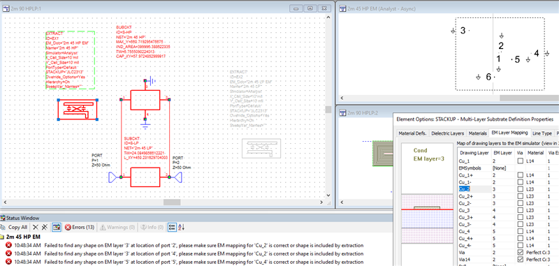
I'm trying out Analyst for EM extractions instead of AXIEM but I cant get the Analyst extraction to work (though AXIEM does). The EM has no metal after extraction and I get errors like this:

10:48:34 AM Failed to find any shape on EM layer '2' at location of port '1', please make sure EM mapping for 'Cu_1' is correct or shape is included by extraction
10:48:34 AM Failed to find any shape on EM layer '5' at location of port '6', please make sure EM mapping for 'Cu_4' is correct or shape is included by extraction
10:48:34 AM Extraction Failed.

I've attached the project as a .emz, just push F8 and you'll see the error, we are using AWRDE 15.04r build 100117 Rev2

Here's a screenshot.  Clearly EM layer 2 is mapped to Cu_1 and EM layer 5 is mapped to Cu_4.

What am I missing here?

-Eric

Plotting Phase Noise for Injection Locked Ring Oscillator

$
0
0

Hi, I am using spectre -W( subversion 15.0.1.257) virtuoso -W(subversion IC6.1.7-64b.500.10). And I am trying to plot the Phase Noise for the Injection Locked Ring Oscillator for the Schematic shown.

But when I try to do the PSS(Shooting Engine) and PNOISE Analysis, it gives an error that PSS did not converge.

This is the Setup I have done for doing the PSS analysis.

And from the options I selected gear2.

Is this setup correct for doing the PSS Analysis for Injection Locked Ring Oscillator?

I really appreciate any help you can provide.

Variable for noisefile in vsource

$
0
0

Because I want to sweep noise profile of a dc source in Assembler, I put a variable (f_vctrl) for the noise file name and use something like "path1","path2" in the corner settings.

But then the simulation report file not found error. I found in the netlist that the parameter had " " added to the variable. I guess this is the cause to the error.

The same approach is applied to nport and its sparameter file name in the same test bench and working fine.


How should I correctly sweep the noise file name for vsource? 

I cant find PACmag in cadence

$
0
0

Hi guys.

I have a really silly question. I'm using cadence IC617 and I can't find the location in which to set up PAC magnitude for PAC analysis. I tried PORT and Vsource but the only thing that is available is AC magnitude, not PAC!

I attached a pic of my PORT's property window.

appreciate ur help!

Passivity violation in S param file

$
0
0

Hi everybody, 

I am designing LNA  whose testbench uses some S-parameter files for off-chip components from vendors(L,C, balun...). the warning arises as in the logfile below 

I think that it is due to the frequency range in S-param files does not go down to 0 frequency point or even not close to such the lower point (10 Mhz or  1Mhz..) . It is tough to change it without each component measurement..

Is that affect the accuracy of frequency response and other merits at other frequencies ( in terms of gain, noise, and oip3....).. I am aware that a violated passivity of S-param can possibly impact on stability and causality at a single frequency point (correct me if I'm wrong). 

Thanks, 

Binh Ngo

Viewing all 956 articles
Browse latest View live