Quantcast
Channel: Cadence RF Design Forum
Viewing all 956 articles
Browse latest View live

modulated PAC analysis

$
0
0

Hi, I am currently using Virtuoso IC6.1.6 and running SpectreRF simulation in MMSIM151. I am attempting to run a modulated PAC simulation. Please see my setup below:

One thing I do not know is the meaning of "Output Upper Sideband". Also, if I switch the "Input Type" from SSB to "SSB/AM/PM", "Output Upper Sideband" changes to "Input Modulated Harmonic" as seen below:

My understanding in this case is that it is supposed to set the input frequency range (only one can be chosen). But isn't this already set from the Relative harmonic and frequency sweep range specification? 

I have found very scarce documentation on this field. Any help is appreciated.

regards,

SC


The impedance frequency response of Large signal and periodic circuit

$
0
0

Hi ,i'm designing LC VCO and i want to simulate the frequency response of the tank impddance.At first, i use the sp simulation.

But i realize that the small signal sp simulation is not suitable for the large signal circuit like VCO,because the operation point of mos tansistor is time-varying.

So,is there any solution.thanks.

LVS can't identify layout inductor

$
0
0

Hello Everyone,

My inductor in layout can't be identified in assura LVS. As shown below, it shows that inductor is unbound to any layout device. I also tried Calibre LVS, which also has the same problem. In calibre lvs, the report shows that missing inductor (bad device). Could anybody help me with it? Is my setting not correct? 

Simulating invertion layer(channel) creation time in MOSFET

$
0
0

Hello, I have an issue that my data  falling edge is very close to the clock rising edge, thus logic '1'  doesnt get sampled as you can see in the arrows in the last photo
so i got to the conclution that altough we have VDD at the gate there has to pass some minimal time for the mosfet to create an invertion layet(channel)

is there a way to simulate and see this amount of time in cadence virtuoso?
Thanks

Can we generate LTE Modulated Signals in Spectre RF ?

$
0
0

Hi Cadence Community,

I am actually a University student and wanted to know if we can generate modulated signals for LTE (I need to generated 80MHz LTE signal) in spectreRF using the envelope analysis ?

Thanks in Advance,

Sumit Bhardwaj

multiple gnd's passive components only system problem

$
0
0

Hello , i have a system with multiple device represented by R L C components each device has its own ground, i wanted to make POLE ZERO simulation on it.

at first for the simplisity i made  all the devices stacked and one big cirtuit(which was verified in a much simpler simulator called LTSPICE)

After that i tried to convert each device as a symbol as shown bellow.
when In cadence virtuoso i didnt use symbol to simplify the schematics it gave me errors like,

1.no DC path from node "net.. to ground" Gmin installed to provide a path

2.Fatal: the following braches form a loop of rigid barnches(shorts) when added to the circuit

3.why i tried to make subsimbols it gave me an error in bettween the connection of the devices saying they are floating although they are not(and i ran it fine in LTSPICE)

i really want to use the potential of cadence virtuoso to analyze to the fullest extent this passive component network

Where did i go wrong?

Thanks

Print Noise Summary. What is the noise unit for currents?

$
0
0

Hello everybody,

I am comparing my noise simulations with the calculations.

If I print the noise summary (spot noise), I can select either V^2 or V.

By selecting V^2, at the end of the printed list there is this sentence:

"Spot noise Summary (in V^2/Hz)..."

However, in the printed list there are current noise densities as well (id, igs, igd, igb).

For example, i get

id    4.60029e-15

What is the unit for these current densities? Should I interpret it as  A^2/Hz? Or is it multiplied by something to get the unit V^2/Hz? 

Thanks!

how to plot MOS Capacitors(cgs,cgd) with respect frequency ?

$
0
0

hi all

In RF IC DESIGN i want to know that frequency response of mosfet parasitic capacitance .


complex pole zero simulation into matlab bode plot

$
0
0

Hello, after succseeding to confirm with a simple circuit an AC sweep  with Matlab bode plot of pole zero simulation out put, i tried to match similarly a more complex circuit  which beyong poles and zeros

also gave me output a significant Constant factor DC gain, futher more the peaks frequency  in matlab bode plot and in AC sweep didnt match.(As shown in the plots bellow)

I Have attached the pole zero simulation output txt file,the circuit netlist, and the MATLAB script transfer function that was built from the pole zero simulation output(the post didnt allow me to upload a *.m file)

where did i were wrong defining the transfer function?

community.cadence.com/.../1803.netlist.txt

community.cadence.com/.../pole_5F00_zero_5F00_output.txt 

 community.cadence.com/.../matlab_5F00_script.txt

RF Average power calculation

$
0
0

Hello friends,

May I ask if someone knows how to calculate the average power delivered to a load? I'm running a HB simulation and the equation that I would like to use is the 0.5*V*conj(I), which is the same thing we use in ADS. Unfortunately, in the calculator, we only have access to the transient, AC and DC voltages and currents. I would like to calculate the amount of power delivered to a load (not necessarily 50 ohms) as a load of a PA.

Thanks,

Soroush

Calculator function to check conditions on 3 (or N) waveforms

$
0
0

Hello,

I have a question about the use of calculator functions.

As an output of an s-parameter (or ac) simulation, I have three custom waveforms a_w, b_w, c_w which are all functions of frequency, i.e.  a_w(f), b_w(f), c_w(f).

I would like to check these waveforms to see if there is any frequency point "f0" satisying:

1) a_w(f0)<0

2) b_w(f0)=0

3) c_w(f0)>0

without visual observation on the graph.

Is there a way to do this using cadence calculator?

My cadence version is IC6.1.7-64b.500.23.

Thanks in advance.

passive mixer-first receiver IIP3 simulation: IM3 curve not 3dB/dB

$
0
0

Hi,

I design a common passive mixer-first receiver(passive mixer +TIA) in TSMC65LP  CMOS process. In the test bench, I drive the receiver with a port , then a idea_bulun , then an ac coupling capacitor connect to the receiver. I use HB method to simulate the IIP3 of the receiver(Lab 10: IP3 Calculation (hb with Three Tones)  ). I have two questions: 

1. why the IM3 curve is not 3dB/dB ?

2. when I set different "number of harmonics"(from auto 3 3 to 3 2 2), the IM3 curve change greatly, but the slope is still  non-monotonic. 

Why is the difference so significant and how can I simulate the correct curve ?

Thank you!

plotting gm of DC simulation without file creation

$
0
0

Hello  i am trying to plot gm of DC simulation by showing the  gm in the result browser


The way i found  to do it is by  creating a file  with a single line  "SAVE M0:all" save it as scs file and put it as a stimulus file as shown bellow.

However i am running my projects from a very restricted LINUX server i dont have the ability to create files or change directories..(i only can run cadence virtuoso)

Is there an alternative  way to create a gm plot without creating a file?
Thanks

region annotation on mosfet

$
0
0

Hello , i am trying to set my transistor into saturation, i have tried results->annotaion->DC operation point as shown bellow.

I need it to show the region parameter near the mosfet.

How could it be done?

Thanks

generating calibre view costs too long time

$
0
0

hi everybody

I am using calibre to extract parameters of the layout, and I choose calibreview in the pex option. when i run pex, the "*.pex.netlist file" can be generated successfully(the "*.pex.netlist" file is about 200M), but after i set up the calibre view window, it costs too long time to generate calibre view successfully(generally 1day or more). how to generate the calibre view faster? 

thanks~


Common Gate

$
0
0

Hello Everyone,

My problem is that the Common gate gives me negative/little gain unless I use a VCVS at the output before the Port.

I am currently trying to design a Balun LNA, so it is important to test the CG amplifier.

Thank you.

Running multiple PAC simulations on the same PSS analysis

$
0
0

Dear All,

I am trying to run PAC analysis for multiple i/p frequency values.

Can it be done without running PSS multiple times if so, how it can be done.

Kind Regards,

Regarding the PNOISE analysis Form for sampled Noise analysis

$
0
0

Dear All,

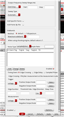
I am seeing the PNOISE analysis form for sampled case, as below:-

For, Edge Crossing mode, I see Edge Number and Sleep time.

I am confused here.

Like PAC/PXF, the pnoise should have Thresold Value and Edge Direction options.

But, what is the use of Edge Number and Sleep TIme here ?

Can anybody please clarify on this.

How to capture the Sampled PAC/PXF results at a given frequency/sideband using OCEAN command.

$
0
0

Dear All,

I want to capture the Sampled PAC/PXF results at a given frequency/sideband using OCEAN command.

For, sampled results, we have to use only spectrum NOT sideband.

I am NOT able to find the OCEAN/SKILL command which can capture the Spectrum results at  a given frequency.

In other words, Spectrum gives you values around all sidebands:- k* F_LO + Delta_f.   Delta_f is the frequency range given on the PAC Form in absolute sweep mode. Assume Delat_f is varied from 0.1KHz to 0.2KHz in step of  0.1KHz.  and F_LO=1GHz

Now, I want capture the values at        :-  ...-2*1GHz + 0.1KHz, -1*1GHz + 0.1KHz, 0.1KHz, 1*1GHz + 0.1KHz,2*1GHz + 0.1KHz..... and write into a file.

How, I can I get those values using OCEAN command.

Kind Regards,

What is the difference between DC operating parameters ron and gds of MOS

$
0
0

Dear All,

Cam naybody please tell what is the difference between DC operating parameters ron and gds of MOS.

Is ron=1/gds ?

Kind Regards,

Viewing all 956 articles
Browse latest View live